Tender-Grade Quality
Bernoullis Theorem Demonstration Module
Export Worldwide
Full Documentation
Made in India
- Response within 1 business day
- Global logistics
- Tender-ready docs
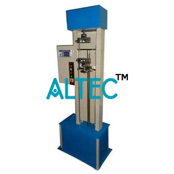
Bernoullis Theorem Demonstration Module
• All the pressure taps are connected to a manometer with a water collector (water might be pressurized).
• The ends of the conduits are removable, enabling to be placed in either convergent or divergent form with respect to the stream direction.
• For the operation, the module is placed on the Hydraulics bench top It has adjustable legs for leveling.
• Adjusting the control valve located at the end of the module can modify the flow rate and the pressure in the module.
• A flexible hose attached to the outlet pipe is directed to the volumetric measuring tank.
• The inlet pipe ends in a female coupling, which may be directly connected to the bench supply.
• There is also a probe (Pitot’s tube) moving along the conduit or measuring the height in every section (dynamic pressure).
• Narrowing: Downstream: 21°.
• Upstream: 10°.
• Manometer range: 0 to 300 mm of water.
• Number of manometer tubes: 8.
• Upstream diameter of the throat: 25 mm.
• Dimensions: 800 x 450 x 700 mm. approx.
• Weight: 15 Kg. approx. (33 pounds approx.)
• Anodized aluminum/ MS powder coated structure and panel of painted steel.
To request a quotation for Bernoullis Theorem Demonstration Module (Product Code EEMECH45M0047), share your tender BoQ or requirement list by:
- Email: sales@equipmentsexporters.com
- Phone: +91 9311469084
- WhatsApp: +91 9311469084
Quotation turnaround is typically 24-48 hours with brochures, datasheets and a priced compliance statement.