Deformation of Frames
- Response within 1 business day
- Global logistics
- Tender-ready docs
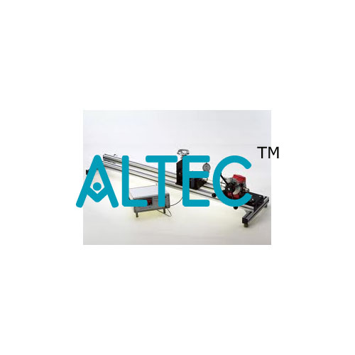
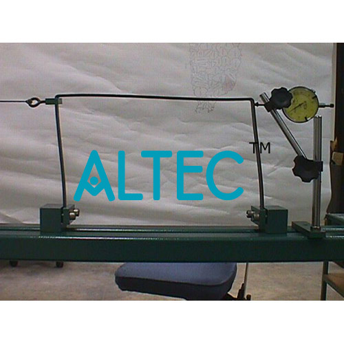
A frame is a bent beam with rigid corners which creates a so-called structure gauge. This means that it spans a gap while at the same time creating height. This is includes a typical U-shaped frame, such as is used in the construction of halls for example. One end is clamped into place, while the other can be loosely mounted. When the non-clamped end remains free, the statically determinate frame is investigated. A roller bearing on the non-clamped end creates a statically indeterminate frame. The frame is placed under load by two sets of weights. The load application points are movable. Two dial gauges record the deformations of the frame under load. By applying various methods (first-order elasticity theory; the principle of superposition; and the principle of virtual work), the bending moment characteristics are ascertained for a statically determinate and indeterminate frame. From these characteristic curves and a chart for integrals (coupling table) the differential equation of the bend line is formulated. From the bend line and its derivations, displacements and the support force on the movable support can be calculated. A second, S-shaped frame can be used to show that the various methods are applicable to any kind of frame. The various elements of the experiment are clearly laid-out and housed securely in a storage system. The complete experimental set-up is arranged in the frame.The well-structured instructional material sets out the fundamentals and provides a step-by-step guide through the experiments.
Specification:
1. Investigation of the deformation of steel frames under load
2. U-shaped and S-shaped frame
3. Statically determinate or statically indeterminate bearing support possible
4. 1 long and 1 short clamping pillar
5. Roller bearing for statically indeterminate support
6. Loading of the frame by weights
7. 2 sets of weights with a movable hook to adjust to any load application point
8. Dial gauges record the deformation of the investigated frame under load
9. Storage system to house the components
10 Experimental set-up in frame.
Technical Data:
Frame made of steel
- edge length: 600mm
- cross-section: 20x10mm
- U-shaped: 600x600mm
- S-shaped: 600x600mm
Dial gauges
- measuring range: 0…20mm, graduations: 0,01mm
Weights
- 2x 1N (hanger)
- 8x 1N
- 6x 5N
Detailed technical specifications, datasheets and brochures available on request. Email sales@equipmentsexporters.com with your tender BoQ for itemwise specifications.
To request a quotation for Deformation of Frames (Product Code ALABS-A180-018), share your tender BoQ or requirement list by:
- Email: sales@equipmentsexporters.com
- Phone: +91 9311469084
- WhatsApp: +91 9311469084
Quotation turnaround is typically 24-48 hours with brochures, datasheets and a priced compliance statement.